Home

radioactividad discreción de ts diagram refrigeration Manhattan mezcla diferente a

T-s diagram of the vapour-compression refrigeration cycle considered in...  | Download Scientific Diagram
T-s diagram of the vapour-compression refrigeration cycle considered in... | Download Scientific Diagram
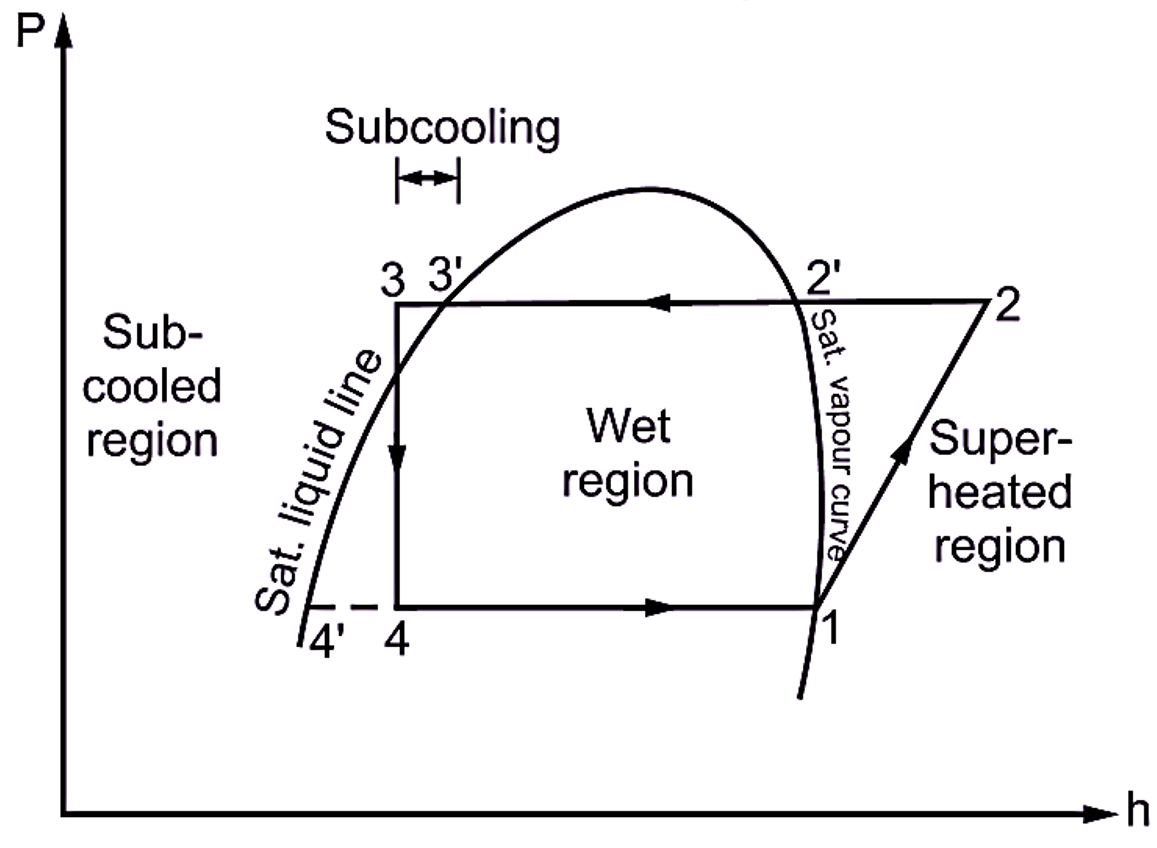
What is Subcooling in Refrigeration System? Explanation & Process -  ElectricalWorkbook
What is Subcooling in Refrigeration System? Explanation & Process - ElectricalWorkbook

Ch10, Lesson C, Page 6 - Increased COP: Multistage V-C Refrigeration Cycle

Solved) - The T-s diagram of a two-stage cascade refrigeration system with  a... (1 Answer) | Transtutors
Solved) - The T-s diagram of a two-stage cascade refrigeration system with a... (1 Answer) | Transtutors
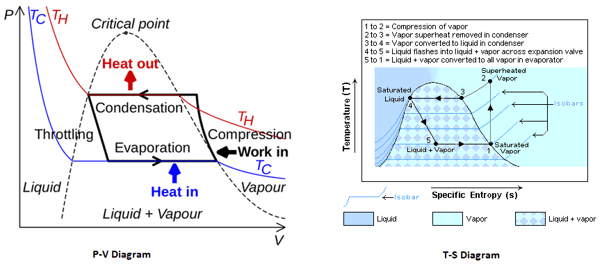
Vapour Compression Refrigeration Cycle: - Engineering Tutorials

REFRIGERATION
REFRIGERATION

Ch10, Lesson E, Page 5 - TS Diagram for the Regenerative Cycle

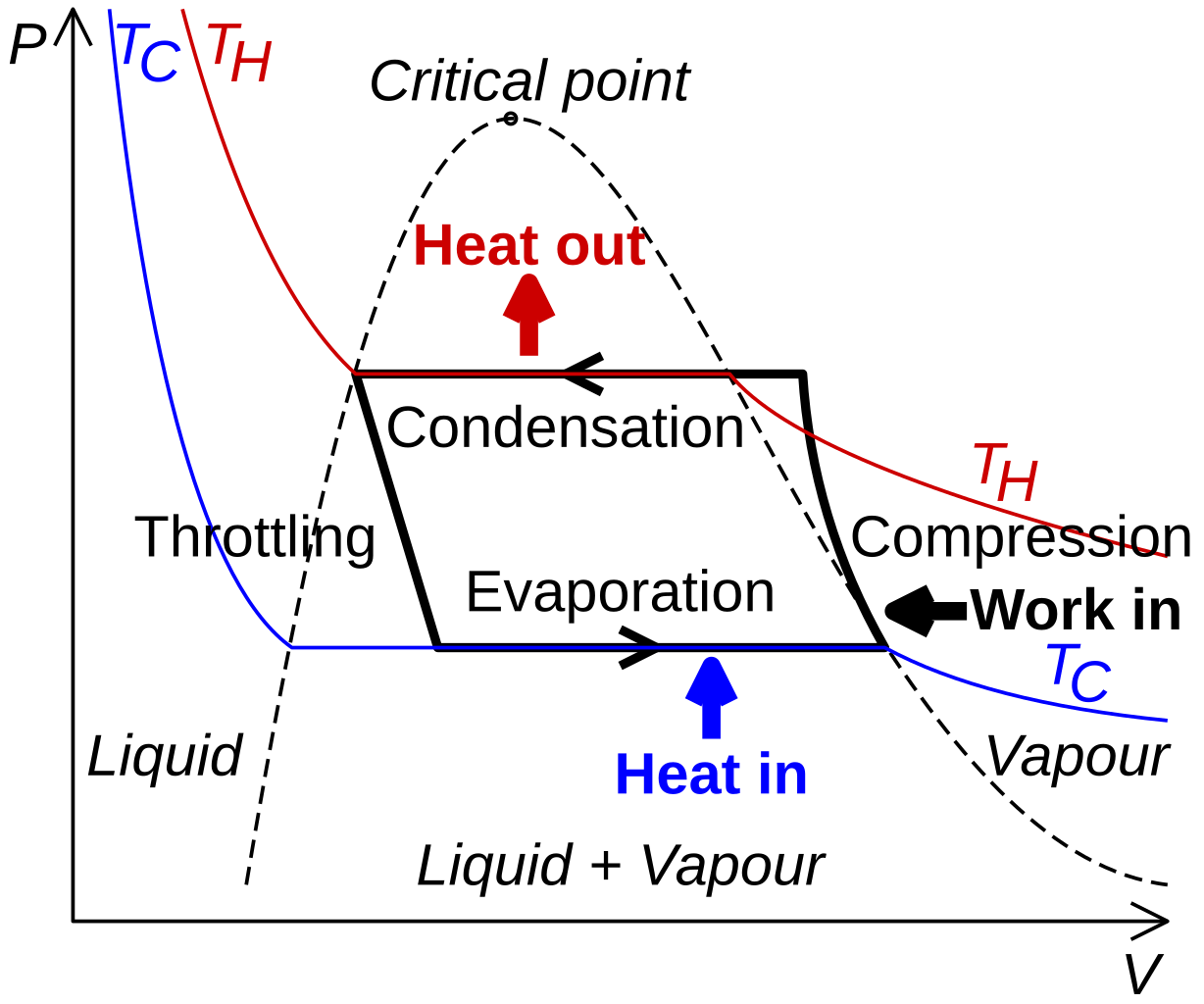
Heat pump and refrigeration cycle - Wikipedia

Mechanism And Working Of A Vapour Compression Refrigeration System - With PV  And TS Diagram | Mecholic
Mechanism And Working Of A Vapour Compression Refrigeration System - With PV And TS Diagram | Mecholic

Ideal refrigeration cycle T-s diagram; 1→2: isobaric cooling and... |  Download Scientific Diagram
Ideal refrigeration cycle T-s diagram; 1→2: isobaric cooling and... | Download Scientific Diagram

Design of Vapor-Compression Refrigeration Cycles

A vapor compression refrigeration system circulates refrigerant 134a at a  rate of 6kg/min. The refrigerant enters the compressor at -10 o C, 1.4 bar,  and exits at 7 bar. The isentropic compressor
A vapor compression refrigeration system circulates refrigerant 134a at a rate of 6kg/min. The refrigerant enters the compressor at -10 o C, 1.4 bar, and exits at 7 bar. The isentropic compressor

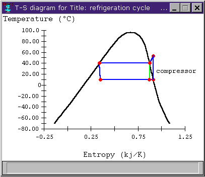
Schmatic and T-s Diagram for Ideal Vapor-Compression Refrigeration Cycle

Vapour Compression Refrigeration | Working with pv and Ts diagram | RAC |  Sourav Kumar - YouTube
Vapour Compression Refrigeration | Working with pv and Ts diagram | RAC | Sourav Kumar - YouTube

Property diagrams TS and PH for refrigeration 2 - YouTube

Property diagrams TS and PH for refrigeration - YouTube

Draw T-S and P-H diagram of sub-cooled and super heat vapour compression  refrigeration cycle and name the processes.
Draw T-S and P-H diagram of sub-cooled and super heat vapour compression refrigeration cycle and name the processes.

File:Refrigeration PV diagram.svg - Wikimedia Commons

Refrigeration Cycle Diagram Explained - Refrigeration - HVAC/R & Solar

Bell Coleman Cycle with PV and TS diagram – Mechanical Walkins

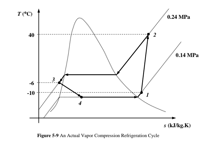
Solved Figure 5-9 shows a T-s diagram for an actual | Chegg.com

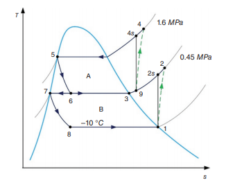
T-s diagram of a cascade refrigeration cycle | Download Scientific Diagram

Draw P-H and T-S diagram when the vapours are superheated at the end of  compression and with under cooling of liquid
Draw P-H and T-S diagram when the vapours are superheated at the end of compression and with under cooling of liquid